s(M)exoscope
Reviving the classic oscilloscope plug-in from smartelectronix
For years I’ve been using Bram & Sean’s s(M)exoscope to inspect the waveform output of my plug-ins. It’s a very useful debugging tool. Recently I upgraded — finally! — to an ARM-based Mac and could not find a version of s(M)exoscope that runs natively on Apple Silicon.
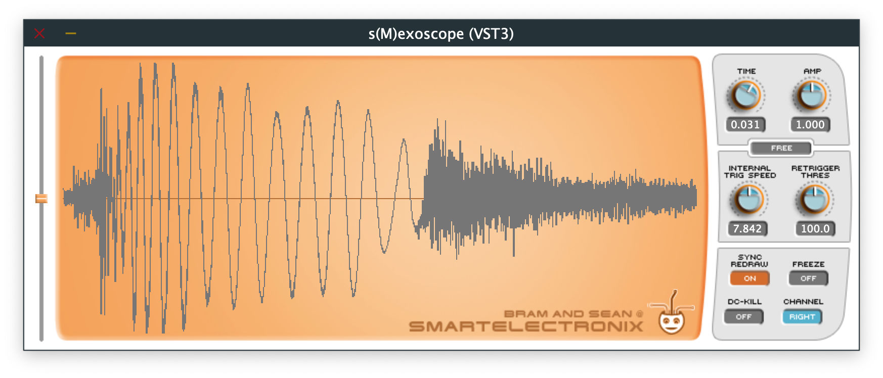
So I decided to port the plug-in to JUCE and build it for modern systems. It turned out that the version I’d been using all this time (from Armando Montanez) actually was made with JUCE already, just an old version. So that saved me a lot of work!
Still, I decided to clean up the code and document the inner workings as part of my Plug-in Archeology project. After all, the original is from 2003 so that qualifies as ancient. 😉
You can find the code and VST3/AU downloads on GitHub.
The GUI
The SmexoscopeAudioProcessorEditor class is the main editor. It draws a big background image and has knobs, buttons, and text labels as child components.
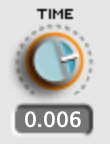
The knobs are instances of the CustomKnob class. This is a juce::Slider that draws an image from a filmstrip. The knob is 33×33 pixels and the filmstrip image contains 75 states.
Note: The graphics are from before Retina and HiDPI screens, so they may look at little blurry but it’s not too bad. It would be cool to do an update of this plug-in with high-resolution graphics.
The number below the knob is the TextElement class, a simple juce::Component subclass that draws a numeric value. JUCE sliders can have a text box attached to them but here we just use a read-only label — you cannot type new values into this component.
One of the small improvements I made was enabling double-clicking on the knobs to reset them to their default value. That’s something I always wished for in this plug-in.
The buttons are instances of another custom class, MultiStateButton. Tapping this button cycles through the images in a filmstrip. For example, here is the filmstrip PNG file for the trigger mode button:

On the left of the window is a vertical slider, CustomSlider, which is also a subclass of juce::Slider. It paints a little handle image at the position for the slider’s current value. The gray track is part of the background image.
All these UI controls are pretty basic and there isn’t much more to say about them. The only thing to keep in mind is that they all assume their value is in the range 0.0 - 1.0, even the buttons. None of these components are styled by the look-and-feel system, by the way. They simply override the paint() function.
The final UI component is the WaveDisplay class, which draws the captured waveform in the main area of the screen. More about this class later.

Something I never realized is that the little logo face in the bottom-right corner randomly changes whenever you load the plug-in. A fun little easter egg that I completely missed until I read the source code!
The parameters
s(M)exoscope has the following parameters:
TIME — How much of the waveform is visible at once. This lets you zoom in/out on the horizontal axis. The number shown below this knob isn’t very intuitive and I never really knew what it meant until I studied the source code. It is the number of pixels per sample!

-
With the TIME knob at 0%, we get 31.62 pixels per sample. Strange number but oh well. Since the scope is 627 pixels wide, this will fit about 20 sample points, so this is super zoomed in.
-
At the other extreme, with TIME at 100%, this is 0.0003162 pixels/sample. Put differently, we now get 3162 samples per pixel, meaning the display will fit almost 45 seconds of audio at 44.1 kHz.
-
The default setting is about 178 samples per pixel for approximately 2.5 seconds of audio. Fun fact: When the TIME knob is at 30%, there is exactly one pixel per sample.
Note: Why these weird numbers? No idea but an old comment in the code makes me believe the zoom level used to range from 10 pixels/sample to 1000 samples/pixel and at some point it got changed.
AMP — Applies gain to the input signal for zooming in/out on the vertical axis. Goes from 0.0001 to 1000.0, which means –60 dB to +60 dB. If you boost gain too much, the samples are clipped against the edge of the scope.
TRIGGER TYPE — The trigger determines when the oscilloscope restarts its measurement. In FREE mode it simply loops back to the beginning when it reaches the end of the screen. In RISING and FALLING mode, it checks if the samples have crossed a threshold set by the user. In INTERNAL mode it runs an internal oscillator at a certain speed and triggers after each period.
TRIGGER LEVEL — This is the vertical slider on the left of the window. It becomes active when the trigger type is RISING or FALLING. The height of the slider sets the threshold that must be crossed by the signal in order to trigger the oscilloscope.
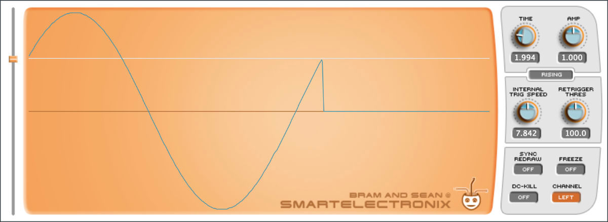
INTERNAL TRIG SPEED – When the trigger type is INTERNAL, this sets the speed of the internal oscillator. Oddly, the values for this knob depend on the current sample rate, which perhaps is indicative of the era this plug-in was made in where everyone used 44.1 kHz for everything.
To see how this works, send a sine wave of 220 Hz into s(M)exoscope and set the trigger to INTERNAL, the trigger speed to 110 Hz. You should see two periods of the sine wave being drawn on the screen.
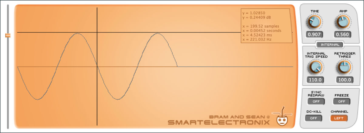
Clicking anywhere in the scope brings up a panel with useful information. Really handy for measuring the frequency or amplitude of a signal. Here it indeed shows that the sine wave has a frequency of 220 Hz. You can right-click to dismiss this panel.
RETRIGGER THRES — To avoid a signal from triggering too often, use this knob to set the minimum number of samples that must have passed before the next trigger may hit. This is a value between 1 and 10000 samples.
SYNC REDRAW — If enabled, the screen will not be redrawing constantly but only when the trigger was hit. With this disabled the oscilloscope can show glitches, but this is mostly because there are data races between the audio and UI threads… 😅
FREEZE — If enabled, the plug-in simply ignores any new input and keeps showing what was already on the screen.
DC-KILL — Enables a high-pass filter that removes any DC offset from the input signal. This will center the signal in the scope.
CHANNEL — Whether to read from the left or right input channel when using a stereo input signal.
For more info, check out the user manual that came with the original s(M)exoscope.
How the parameters are implemented
Bram’s original code, which uses the VST2 SDK, exposes the above settings as parameters to the DAW but Armando’s JUCE port doesn’t. It never calls addParameter() and the APVTS didn’t exist yet back then. I guess it doesn’t really matter because not a lot of people would need to automate the parameters of an oscilloscope.
The Smexoscope class has an enum for these parameters:
enum
{
    kTriggerSpeed,  // internal trigger speed, knob
    kTriggerType,   // trigger type, selection
    kTriggerLevel,  // trigger level, slider
    kTriggerLimit,  // retrigger threshold, knob
    kTimeWindow,    // X-range, knob
    kAmpWindow,     // Y-range, knob
    kSyncDraw,      // sync redraw, on/off
    kChannel,       // channel selection, left/right
    kFreeze,        // freeze display, on/off
    kDCKill,        // kill DC, on/off
    kNumParams
};
It simply stores the corresponding parameter values into an array of floats:
std::atomic<float> SAVE[kNumParams];
This used to be a regular float but I made it atomic because we’ll need to access the parameters from both the audio thread and the UI thread.
The methods to write and read these parameters directly access this float array:
void Smexoscope::setParameter(int paramIndex, float value)
{
    SAVE[paramIndex] = value;
}

float Smexoscope::getParameter(int paramIndex) const
{
    return SAVE[paramIndex];
}
Loading and saving the plug-in state is simply a matter of memcpy‘ing the array into / out of a juce::MemoryBlock. This happens in the main plug-in class:
void SmexoscopeAudioProcessor::getStateInformation(juce::MemoryBlock& destData)
{
    destData.setSize(smexoscope.getSaveBlockSize());
    destData.copyFrom(smexoscope.getSaveBlock(), 0, smexoscope.getSaveBlockSize());
}

void SmexoscopeAudioProcessor::setStateInformation(const void* data, int)
{
    std::memcpy(smexoscope.getSaveBlock(), data, smexoscope.getSaveBlockSize());
}
Other than that, the host will never see any of these parameters. It just gets a binary blob of data that it needs to store somewhere. Pretty crude but it works fine.
The editor class, SmexoscopeAudioProcessorEditor, reads the current parameter values in its constructor and assigns them to the knobs and buttons, like so:
SmexoscopeAudioProcessorEditor::SmexoscopeAudioProcessorEditor(...)
{
    timeKnob.setValue(effect.getParameter(Smexoscope::kTimeWindow));
    ampKnob.setValue(effect.getParameter(Smexoscope::kAmpWindow));
    // and so on...
Here, effect is a reference to the Smexoscope object.
Note: This approach only works correctly if setStateInformation() is called by the host before the editor window is constructed, but that generally seems to be the case. Except if you use the host’s preset facility to load a preset into s(M)exoscope — you’d need to close and open the plug-in’s window again.
The editor also starts a timer that will repaint the waveform 30 times per second and also calls a function updateParameters() that reads the values from the knobs and buttons and assigns them back to the Smexoscope object again:
void SmexoscopeAudioProcessorEditor::updateParameters()
{
    effect.setParameter(Smexoscope::kTimeWindow, float(timeKnob.getValue()));
    effect.setParameter(Smexoscope::kAmpWindow, float(ampKnob.getValue()));
    // and so on...

    timeText.setValue(...);
    ampText.setValue(...);
    // and so on...
}
To recap, the knobs get the current parameter values when the editor is loaded, and then several times per second we read from those knobs again and update the parameters if they need changing. Of course, this timer runs on the UI thread, which is why I made the values in the SAVE array atomic.
This is a little weird if you’re used to working with an APVTS and parameter attachments or listeners but we can get away with it here because the plug-in redraws the screen 30 times per second anyway.
Mapping the parameter values to the knobs
Since the original code was a VST2, all parameters have values between 0.0f and 1.0f.
For example, even though the AMP knob shows a range from 0.001 to 1000, internally the kAmpWindow parameter is always between 0 and 1.
The conversion from this normalized value to an actual number that we can display is done in the editor’s updateParameters() function, like so:
ampText.setValue(float(std::pow(10.0, ampKnob.getValue() * 6.0f - 3.0f)));
Here, ampKnob.getValue() is a float between 0 and 1. If we fill in a few different values into the above formula, we get the following results:
| value | calculation | result | decibels |
|---|---|---|---|
| 0.0 | pow(10, –3) | 0.001 | –60 dB |
| 0.25 | pow(10, –1.5) | 0.0316 | –30 dB |
| 0.5 | pow(10, 0) | 1.0 | 0 dB |
| 0.75 | pow(10, 1.5) | 31.62 | +30 dB |
| 1.0 | pow(10, 3) | 1000.0 | +60 dB |
In other words, the std::pow() function turns the 0 – 1 value into a skewed number that goes from 0.001 to 1000, with the default value of the knob in the halfway position being 1.0. If you prefer to think about gain in decibels, this gives a range from –60 dB to +60 dB.
Note that this knob displays an exponential amount but is actually linear in decibels, so it feels quite natural to use. One possible improvement might be to switch this knob between dB and linear mode.
The same formula is repeated in Smexoscope’s process() function that performs the audio processing. For some parameters, including the AMP knob, the pow formula also appears in WaveDisplay’s paint() function.
const float gain = std::pow(10.0f, SAVE[kAmpWindow] * 6.0f - 3.0f);
You probably wouldn’t do it like this in modern code but have a JUCE AudioParameterFloat object with a range from 0.001 to 1000 and an appropriate skew factor, so that this pow formula is handled by the parameter object itself rather than in two or three different places in the code.
Sampling the signal
What this plug-in does is pretty straightforward:
-
The
Smexoscopeobject performs the audio processing. This periodically samples the incoming signal and writes the recorded values into an array namedpeaks. -
Every so often (30 times per second) the
WaveDisplayobject reads from thepeaksarray and draws these points to the screen.
Let’s first look at how the audio processing code works. For every input sample it does the following.
-
If the FREEZE option is enabled, do nothing and immediately return.
-
If the DC-KILL option is enabled, apply a simple high-pass filter to the input.
-
Apply gain from the AMP knob and clip the result to the range [–1.0, 1.0].
-
Check to see if the trigger was hit. The different trigger types have different rules. For example, RISING mode triggers when the current sample is over the TRIGGER LEVEL threshold set by the user and the previous sample was below that threshold.
-
However, if the trigger happens within a certain number of timesteps since the previous trigger, cancel it. This is the RETRIGGER THRES parameter.
-
When a trigger happened, reset the state of the oscilloscope so that we start filling up the
peaksarray from the beginning again.If SYNC REDRAW is enabled, at this point we also copy the
peaksarray to a second array namedcopyand make the UI draw from that instead. In this mode, the screen only gets updated when a trigger hits. Whereas thepeaksarray is being written to continuously,copyis overwritten at a much lower rate and therefore the screen doesn’t refresh as often. -
After the number of samples as determined by the TIME knob has passed, add the current sample value to the
peaksarray.
To summarize: The TIME knob determines how often we write into the peaks array. The TRIGGER TYPE determines how often the “electron beam” returns to the left side of the oscilloscope’s display.
The peaks array only has room for 627 readings (the width of the scope in pixels) and it’s possible the trigger doesn’t hit within that time. We’ll simply ignore new readings and stop writing to peaks until eventually the trigger happens.
Note: The original VST2 code also has an FFXTimeInfo class and a TEMPO option for the trigger mode, but this was removed from the JUCE version by Armando and I didn’t feel any urge to put it back. The manual mentions an EXTERNAL trigger mode where some other signal provides the trigger events, but this mode is not present in either version of the code I found. Could use the side chain for that perhaps.
Drawing the waveform
The logic for drawing the waveform is in the WaveDisplay class.
Usually the TIME knob will have a setting larger than 1.0. In that case, one pixel in the oscilloscope’s display needs to represent a whole range of samples, possibly up to 3162 samples per single pixel.
Above, I said the audio processing code stores the current sample value in the peaks array but that isn’t actually true — it stores the largest sample value seen over that period, as well as the smallest sample value. This is why the peaks array holds twice as many points as the oscilloscope is wide:
using PeaksArray = std::array<juce::Point<int>, OSC_WIDTH * 2>;
Personally, I wouldn’t have used Point objects for this but a struct with time, max, and min fields. I think perhaps initially s(M)exoscope stored only one value per timestep (the maximum) but then the author realized that storing the minimum would be useful too and they “hacked” this by having two Points per pixel rather than changing to a new data structure. But I’m just speculating here.
The UI will draw a vertical line between the maximum and minimum value for each of these readings, as seen here:
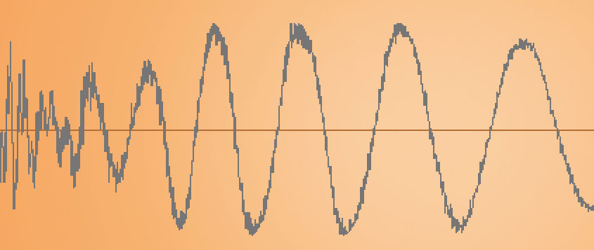
If TIME is less than 1.0, we will store and draw each individual sample (rather than capture the max & min over a range) and there will be unused pixels between the samples. The UI now draws a line segment between each of the sample points, giving a linear interpolation of the signal:

You may notice that this curve can be a little wobbly. That’s because the sample values are float but the audio processing code converts them to integer screen coordinates when they get stored in the peaks array, so what gets drawn isn’t very precise. These days you’d simply draw at fractional coordinates for smoother looking results.
Threads and data races
It’s well-known that two threads may not access the same data at the same time if at least one of them is writing to that data. But that’s exactly what happens here: the audio thread writes to the peaks array (as well as the copy array) and the UI thread reads from it. This will often happen at the same time, creating glitches in the display.
The SYNC REDRAW button is a hacky way around this as it also slows down the rate at which the data is changed. It doesn’t prevent the data race, just makes it less likely.
I’m not sure why s(M)exoscope ignores this cardinal rule of multithreaded programming. Maybe the original authors didn’t know or didn’t care. Arguably it doesn’t really matter: we’re not outputting glitchy audio and the occasional drawing glitch isn’t a big deal. Fair enough, I guess.
One solution would be to use a lock-free FIFO. The audio thread shifts new readings into this FIFO, and when it’s time to redraw the screen the UI thread will grab the latest block of readings and draws that. If I was going to write a new oscilloscope plug-in that’s probably how I’d do it but I didn’t want to change s(M)exoscope too much. The visual glitches are part of its charm. 😃
Note: The Surge XT synth also includes a copy of s(M)exoscope’s WaveformDisplay, so it would be useful to study that code to see how they solved the data race issue.
P.S. Another really nice oscilloscope I like to use is Wave Observer, a great free plug-in.